

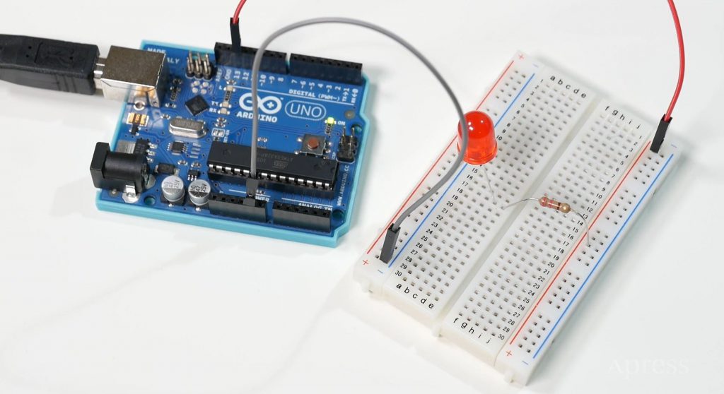
We are going over controlling LEDs with pulse width modulation in the Arduino. We’ll be using the same materials from our previous section on blinking LED, as shown here.
What is Pulse Width Modulation (PWM)?
We can begin to move onto the next stage of LED control, that we’ve flashed an LED, beginning with pulse width modulation. W Analogue control, though, allows for on and off, of course, but all states in between as well. It’s comes in handy when using things like potentiometers to adjust values in increments, which we’ll be looking at later.
Attributes of Pulse Width Modulation?
A digital pin can simulate these attributes with pulse width modulation by pulsing “ON” and “OFF” signals at varying frequencies to create the illusion of analogue control. This occurs so rapidly, though, that to our humanoid eye. We merely see even simulation of whatever outlying we’re upsetting with our code. In this situation, we’ll be consuming PWM to fade an LED on and off effortlessly. To use PWM on our Arduino, we’ll want to yield note of which digital pins we’re using. As single specific digital pins have the aptitude to use PWM precisely, pins 3, 5, 6, 9, 10, and 11. Don’t worry about remembering these details. They are labelled on the panel with a wavy line next to the PIN number to signify PWM. Let’s take our breadboard from the wink circuit. And for now, retain one LED linked to the positive and ground railings.
Arduino Setup
We can preserve the wire for ground associated with the Arduino. But we’ll want to move the wire linked to pin 13, since pin 13 does not have PWM allowed. As an alternative, we’ll interchange the wire to digital pin 9. Now, ample like how the code for blink was comprising as a sample. You’ll find a meek pulse width modulation example as well that we’ll routine to validate this technique. Go to file, models, analogue, and then select diminishing in the Arduino IDE. In watching at the code, we can realize that the pin for the LED is prime inversely than it was in the blink code. This time, existence set up as an integer. There’s no set-up portion for this code. So we can go directly to the loop, which contains two functions to control the PWM.

Bring it to live with Arduino
The initial function permits for the LED to fade up to an “ON” the status by swelling the brightness gradually. PWM values are communicating in our Arduino as oscillating between 0 and 255, with 255 being entirely on. We get in the function that the illumination of the LED is going to increase from 0 to 255 in increases of 5 progressively. We can similarly tell that the determination this function is to grow. The value with the use of a positive equal sign before the 5. This pulse width modulation value is kept in the integer fade value and is then inscribe to the pin with the analogue right command. It’s for the tenacities of the function that the LED’s pin on the Arduino is set of connections as an integer, since analogue right is observing for two integers acceptable to work.
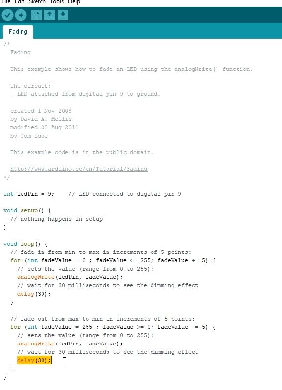
There’s then a postponement for 30 milliseconds, meaning that later the LED has touched its highest brightness, it’ll continue at that brightness for 30 milliseconds. The additional function fundamentally in the pulse width modulation reverses the procedure that the first function presented. As a substitute for increasing the intensity, the illumination is decreasing by augmentations of 5, represented with the minus equals expression. The same range of values are in use like zero to 255, and you’ll realize that the equal declaration of analogue right is using, meanwhile, fade value is still in use in this function. It’s just holding a unique value. There’s an interruption of 30 milliseconds so that the LED will be off for that period. It will have the consequence of continuously blinking fade up and down for the LED once both functions are executing in the loop.
Let’s see this in achievement by compiling the code and uploading it to the Arduino. You should see the LED fading nicely and repeatedly and hope you got the basic knowledge of pulse width modulation.